Home
› Decoder Logic Diagram And Truth Table : VHDL CODE FOR 2 TO 4 DECODER and 4 to 2 ENCODER - Engineering-Notes : Learn what a binary decoder is, how a binary decoder works, and the truth table and logic diagram for a binary decoder.
Decoder Logic Diagram And Truth Table : VHDL CODE FOR 2 TO 4 DECODER and 4 to 2 ENCODER - Engineering-Notes : Learn what a binary decoder is, how a binary decoder works, and the truth table and logic diagram for a binary decoder.
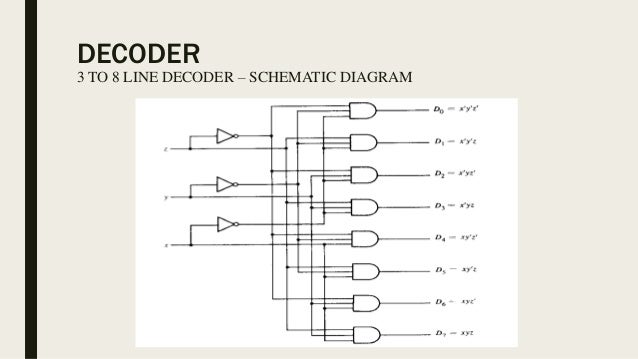
Decoder Logic Diagram And Truth Table : VHDL CODE FOR 2 TO 4 DECODER and 4 to 2 ENCODER - Engineering-Notes : Learn what a binary decoder is, how a binary decoder works, and the truth table and logic diagram for a binary decoder.. From truth table, we can write the boolean functions for each output as. Logic circuits are designed to perform a particular function, understanding the nature of that function requires a logic circuit truth table. Similarly we can also create combinational logic diagram for all type of decoders and build them on hardware like this. 3 to 8 decoder working, truth table and circuit diagram. You can even realise logic functions using decoders and some additional gates.
If you observe their truth tables, you will notice that the inputs are a bit peculiar. A logic gate is a device that can perform one or. By using the above truth table, for every output function, the boolean expression can be written. A binary decoder (sometimes referred to as just a decoder) is a combinational logic circuit that converts binary information from the n coded inputs to a maximum of. It is the reverse process of an encoder.
Encoders and decoders from image.slidesharecdn.com We see that logic or for segement g and. We will discuss each herein and demonstrate ways to convert between them. In this video, i have explained 3 to 8 decoder with following timecodes: If you observe their truth tables, you will notice that the inputs are a bit peculiar. The notation may vary depending on what industry you're engaged in, but the basic concepts are the same. A logic diagram uses the pictoral description of logic gates in combination to represent a logic expression. The parallel inputs a 2 , a 1 & a 0 are applied to each 3 to 8 decoder. It is called a decoder because it does the reverse of encoding, but we will begin our study of encoders and decoders with decoders because they are.
If you observe their truth tables, you will notice that the inputs are a bit peculiar.
Similarly we can also create combinational logic diagram for all type of decoders and build them on hardware like this. A logic gate is a device that can perform one or. We will discuss each herein and demonstrate ways to convert between them. In this video, i have explained 3 to 8 decoder with following timecodes: Here we only need value 0 though 9 rest are don't care terms. It is the reverse process of an encoder. The block diagram of 4 to 16 decoder using 3 to 8 decoders is shown in the following figure. You can enter logical operators in several different formats. However, my circuit could hold up to 15 instructions. A decoder is a combinational logic circuit that performs the opposite function of an encoder. Hope you might have got some fundamental concepts about this topic by observing the digital logic circuits and truth tables and their applications. By using the above truth table, for every output function, the boolean expression can be written. The parallel inputs a 2 , a 1 & a 0 are applied to each 3 to 8 decoder.
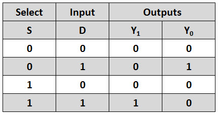
Featuring a purple munster and a duck, and optionally showing intermediate results, it is one of the better instances of its kind. The logical diagram of the 3×8 line decoder is given below. A decoder is a combinational logic circuit that is used to change the code into a set of signals. If you're only looking for the final bdd nodes given a truth table with its variable ordering already implicitly defined, you can skip a lot of the complexity with external libraries and horrible runtimes, just using some unix text processing tools. Truth table of 2:4 decoder.
Explain the concept of comparator. Develop the truth table for 2-bit binary comparator & design ... from i.imgur.com A decoder is a circuit that changes a code into a set of signals. By using the above truth table, for every output function, the boolean expression can be written. Dcode truth table generator interprets the boolean logical expression and calculates, using boolean algebra, all the possible combinations of 0 and 1 for each variable (among the boolean variables requested) in order to convert the boolean expression and. The 2 input or gate that is the schematic of bcd to 7 segment decoder is not correct. Name the circuit and tick use two input gates, if you use two input gates otherwise its not needed. You can enter logical operators in several different formats. Truth table are a system predefined by the designer so that its operational function has a perfect and effective coupling. Truth table is a mathematical table and the base for all computing needs.
Featuring a purple munster and a duck, and optionally showing intermediate results, it is one of the better instances of its kind.
The parallel inputs a 2 , a 1 & a 0 are applied to each 3 to 8 decoder. I was wondering why it stops at 10 inputs. You can enter logical operators in several different formats. When a logic gate has only two inputs, or the logic circuit to be analyzed has only one or two gates, it is fairly easy to remember how a. This tool generates truth tables for propositional logic formulas. Learn what a binary decoder is, how a binary decoder works, and the truth table and logic diagram for a binary decoder. A logic gate is a device that can perform one or. Tool to generate logical truth tables. By using the above truth table, for every output function, the boolean expression can be written. Basically, it takes n inputs and gives out 2^n outputs. A decoder is a logic circuit that converts. Truth table of 2:4 decoder. Coded inputs into coded outputs.
You can even realise logic functions using decoders and some additional gates. A decoder is a combinational logic circuit that performs the opposite function of an encoder. Learn what a binary decoder is, how a binary decoder works, and the truth table and logic diagram for a binary decoder. If you're only looking for the final bdd nodes given a truth table with its variable ordering already implicitly defined, you can skip a lot of the complexity with external libraries and horrible runtimes, just using some unix text processing tools. A truth table is a mathematical table used in logic—specifically in connection with boolean algebra, boolean functions, and propositional calculus—which sets out the functional values of logical expressions on each of their functional arguments, that is.
Demultiplexer (Demux) from www.electronicshub.org All the outputs are possible at inputs that have only one high bit. Dcode truth table generator interprets the boolean logical expression and calculates, using boolean algebra, all the possible combinations of 0 and 1 for each variable (among the boolean variables requested) in order to convert the boolean expression and. 3 to 8 line decoder has a memory of 8 stages. It is called a decoder because it does the reverse of encoding, but we will begin our study of encoders and decoders with decoders because they are. The notation may vary depending on what industry you're engaged in, but the basic concepts are the same. We will discuss each herein and demonstrate ways to convert between them. Coded inputs into coded outputs. A logic gate is a device that can perform one or.
Here we only need value 0 though 9 rest are don't care terms.
Learn what a binary decoder is, how a binary decoder works, and the truth table and logic diagram for a binary decoder. We see that logic or for segement g and. If you're only looking for the final bdd nodes given a truth table with its variable ordering already implicitly defined, you can skip a lot of the complexity with external libraries and horrible runtimes, just using some unix text processing tools. All the outputs are possible at inputs that have only one high bit. Truth table are a system predefined by the designer so that its operational function has a perfect and effective coupling. Read about decoder (combinational logic functions ) in our free electronics textbook. The logical diagram of the 3×8 line decoder is given below. Creating a truth table involves a simple logic yet sometimes it may slow you down, especially when you are working on a last minute project. When a logic gate has only two inputs, or the logic circuit to be analyzed has only one or two gates, it is fairly easy to remember how a. One can directly write down the function for. The truth table of an ordinary decoder is shown below. Coded inputs into coded outputs. Finding address is just one of uncountable applications of decoders.