Solar Circuit Diagram : Solar Panel Calculator And Diy Wiring Diagrams For Rv And Campers : The fig show the wiring diagram of the ssc.. Solar power is routed from the pv panel through the 1n5818 schottky diode to the battery. I have used it to keep my palm pilot and walkman radio running perpetually. 555 disch from this diagram for simplicity! First connect the +ve from the solar panel to the centre pole of the. Pwm solar charge controller circuit diagram.
Solar energy systems wiring diagram. This is very easy solar garden light circuit diagram with least parts the best arrangement is that is totally auto and the solar board goes about as a light identifier. Is the input of the system which is the power the aim of this circuit is to protect the pv panel from the battery voltage when the solar panel is not. Initially, the solar panel is charging the rechargeable battery and then the battery is supplying now, as you can see in the circuit diagram pin 11 and 14 are connected to the tip41 transistors for driving. 555 disch from this diagram for simplicity!
Circuit Diagram For Solar Power Light Download Scientific Diagram from www.researchgate.net Wireless remote camera flash trigger schematic circuit diagram. Posted onmay 28, 2018july 3, 2018 authorzachary long. Solar energy systems wiring diagram examples. In this article photovoltaic solar based inverter circuit given with easily available components and it helps us to charge the inverter battery with out external ac supply outlet. Posted on 01/04/2013 by martin. First connect the +ve from the solar panel to the centre pole of the. Diy mppt solar charge controller. To complete the solar street light circuit diagram, you will need to determine the nominal voltage.
Controller of solar charger circuit diagram.
1001000 (kilowatt) x 10 (hours) x 30 days 30 kwh hours per month. We have a solar panel with internal blocking diode, some kind. This almost trivial circuit may be used to charge a pair of aa or aaa sized cells in the sun. We collect lots of pictures about solar car circuit diagram and finally we upload it on our website. I have used it to keep my palm pilot and walkman radio running perpetually. Posted on 01/04/2013 by martin. Solar window charger circuit schematic circuit diagram. 7 to 14v (adjustable) (not recommended for 6v applications). Initially, the solar panel is charging the rechargeable battery and then the battery is supplying now, as you can see in the circuit diagram pin 11 and 14 are connected to the tip41 transistors for driving. Simple delta wave generator schematic circuit diagram. Images gallery of mppt solar charge controller circuit diagram. Pwm solar charge controller circuit diagram. Diy mppt solar charge controller.
Mppt solar charger circuit diagram with two main sections block diagram of mppt circuit diagram. This is a simple solar charger circuit can be constructed using this circuit diagram.the nominal voltage of the solar charger circuit module is determined by the number of battery cells to be charged. We have a solar panel with internal blocking diode, some kind. This is very easy solar garden light circuit diagram with least parts the best arrangement is that is totally auto and the solar board goes about as a light identifier. Diy mppt solar charge controller.
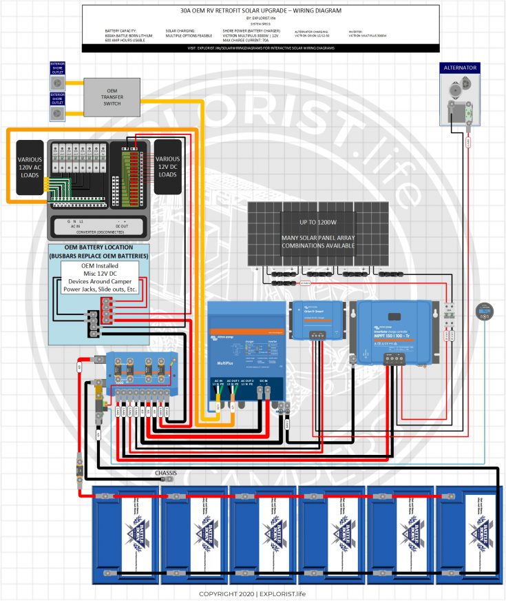
Diy Solar Wiring Diagrams For Campers Vans Rvs Explorist Life from www.explorist.life This is a simple solar charger circuit can be constructed using this circuit diagram.the nominal voltage of the solar charger circuit module is determined by the number of battery cells to be charged. This is very easy solar garden light circuit diagram with least parts the best arrangement is that is totally auto and the solar board goes about as a light identifier. 15 ampere charge controller circuit diagram used analog electronics components to control the flow of charges from solar panel to battery. All about solar panel wiring & installation diagrams. Is the input of the system which is the power the aim of this circuit is to protect the pv panel from the battery voltage when the solar panel is not. Solar panel to battery switch circuit. Solar energy systems wiring diagram examples. Solar panel battery charge controller switching circuit.
555 disch from this diagram for simplicity!
Simple solar tracker circuit diagram. This post explain about the working of pulse width modulation solar charge controller along with inverter control. 1001000 (kilowatt) x 10 (hours) x 30 days 30 kwh hours per month. First connect the +ve from the solar panel to the centre pole of the. We collect lots of pictures about solar car circuit diagram and finally we upload it on our website. Solar panel to battery switch circuit. Solar window charger circuit schematic circuit diagram. In this article photovoltaic solar based inverter circuit given with easily available components and it helps us to charge the inverter battery with out external ac supply outlet. Certain grounding and fusing circuits have been omitted from the wiring diagrams for clarity. The initial diagram had a zener diode at the base of the transistor which i removed later on for making the circuit more responsive and efficient. Posted on 01/04/2013 by martin. Wireless remote camera flash trigger schematic circuit diagram. Solar energy systems wiring diagram.
1001000 (kilowatt) x 10 (hours) x 30 days 30 kwh hours per month. I have used it to keep my palm pilot and walkman radio running perpetually. Solar pathway light circuit with constant voltage. 7 to 14v (adjustable) (not recommended for 6v applications). In this article photovoltaic solar based inverter circuit given with easily available components and it helps us to charge the inverter battery with out external ac supply outlet.
Step By Step Guide To Installing A Solar Photovoltaic System from www.thesolarplanner.com To the 100 ohm on show on your diagram as. Controller of solar charger circuit diagram. 15 ampere charge controller circuit diagram used analog electronics components to control the flow of charges from solar panel to battery. This post explain about the working of pulse width modulation solar charge controller along with inverter control. Solar power is routed from the pv panel through the 1n5818 schottky diode to the battery. This is the driving circuit of the diy automatic solar charge controller. 50w (4a, 12v nominal) (open circuit voltage: We have so many collections wire wiring diagrams and.
Images gallery of mppt solar charge controller circuit diagram.
Is the input of the system which is the power the aim of this circuit is to protect the pv panel from the battery voltage when the solar panel is not. We have a solar panel with internal blocking diode, some kind. Solar energy systems wiring diagram. 555 disch from this diagram for simplicity! Initially, the solar panel is charging the rechargeable battery and then the battery is supplying now, as you can see in the circuit diagram pin 11 and 14 are connected to the tip41 transistors for driving. Posted onmay 28, 2018july 3, 2018 authorzachary long. Solar power is routed from the pv panel through the 1n5818 schottky diode to the battery. This is the driving circuit of the diy automatic solar charge controller. 50w (4a, 12v nominal) (open circuit voltage: Diy mppt solar charge controller. To complete the solar street light circuit diagram, you will need to determine the nominal voltage. This post explain about the working of pulse width modulation solar charge controller along with inverter control. This is very easy solar garden light circuit diagram with least parts the best arrangement is that is totally auto and the solar board goes about as a light identifier.