Home
› Encoder Logic Diagram And Truth Table : Encoder Logic Diagram With Truth Table - Wiring Diagram ... - Decimal to bcd encoder circuit with truth table & circuit diagram.
Encoder Logic Diagram And Truth Table : Encoder Logic Diagram With Truth Table - Wiring Diagram ... - Decimal to bcd encoder circuit with truth table & circuit diagram.
Encoder Logic Diagram And Truth Table : Encoder Logic Diagram With Truth Table - Wiring Diagram ... - Decimal to bcd encoder circuit with truth table & circuit diagram.. 3 to 8 decoder truth table: The logic circuit diagram of 4 2 encoder download scientific. Logic circuits are designed to perform a particular function, understanding the nature of that function requires a logic circuit truth table. The circuit diagram of 4 to 2 priority encoder is shown in the following figure. The 4 to 2 encoder consists of four inputs y3, y2, y1 & y0 and two outputs a1 & a0.
Encoders are combinational logic circuits and they are exactly opposite of decoders. Demultiplexer in digital electronics block diagram truth. Binary encoders basics working truth tables circuit diagrams. An encoder is a device that converts the active data signal into a coded message format. At any time, only one of these 4 inputs can be '1' in order to get the respective binary code at the output.
Encoder Logic Diagram With Truth Table - Wiring Diagram ... from image.slideserve.com Diagram logic diagram truth table full version hd. Priority this modified encoder is known as a priority. Booleon logic truth tables logic gates venn diagrams. A logic accounting for some concept of change, would need need to include some concept of state, essentially internalising the notion of a state of affairs (at least. The encoders and decoders are designed with logic gates such as and gate. On the contrary, a decoder accepts binary code as its input. Binary encoders basics working truth tables u0026 circuit. You can enter logical operators in several different formats.
13:54 sokra academy 185 344 просмотра.
At any time, only one of these 4 inputs can be '1' in order to get the respective binary code at the output. Making a venn diagram look like a karnaugh map. Difference between encoder and decoder. From the truth table, the outputs can be expressed by following boolean function. Encoders are combinational logic circuits and they are exactly opposite of decoders. 13:54 sokra academy 185 344 просмотра. Encoder a block diagram b logical truth table c schematic. The 4 to 2 encoder consists of four inputs y3, y2, y1 & y0 and two outputs a1 & a0. Inspired by this, an increasing number of scientists have attempted to develop logic devices 1 based on dna due to their potential for mimicking the functions of silicon circuitry at the molecular scale in extensive research. Binary encoders basics working truth tables u0026 circuit. This tool generates truth tables for propositional logic formulas. An encoder essentially performs the reverse of a decoder function in a combinational logic. 4 decoder can be done in different methods like using case.
Logical circuit of the above expressions is given below: They accept one or more inputs and generate a multibit output code. The truth table of octal to binary encoder is shown below. Truth table of 2:4 decoder. Logic diagram and truth table.
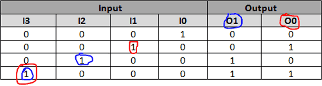
Pin on Electronic Circuit Diagrams from i.pinimg.com The truth table of 4 to 2 encoder is as follows A 1 =y 3 +y 2 a 0 =y 3 +y 1. Truth table of the encoder the decoders and encoders are designed with logic. An encoder is a device that converts the active data signal into a coded message format. A logic accounting for some concept of change, would need need to include some concept of state, essentially internalising the notion of a state of affairs (at least. Does my truth table correct? Read or download logic diagram and truth table for free truth table at diagramadores.giuseppeveneziano.it. The circuit diagram of 4 to 2 priority encoder is shown in the following figure.
Thus one has to drive high on the enable.
Encoders and decoders types and its applications. A logic diagram uses the pictoral description of logic gates in combination to represent a logic expression. Find 4:2 encoder, 8:3 encoder and 4:2 priority encoder circuit, truth table and boolean building encoders using combinational logic designs. Now that we know how an encoder 4:2 encoder circuit diagram: Logic gates truth tables pdf. Encoder logic diagram with truth table. Karnaugh maps, truth tables, and boolean expressions. Decimal to bcd encoder circuit with truth table & circuit diagram. Truth tables simply represent the state of affairs (the facts, if you will) of the world we are considering. Truth table of 2:4 decoder. A 1 =y 3 +y 2 a 0 =y 3 +y 1. Inspired by this, an increasing number of scientists have attempted to develop logic devices 1 based on dna due to their potential for mimicking the functions of silicon circuitry at the molecular scale in extensive research. Making a venn diagram look like a karnaugh map.
Create truth tables with this free truth table generator online. A logic accounting for some concept of change, would need need to include some concept of state, essentially internalising the notion of a state of affairs (at least. The truth table of octal to binary encoder is shown below. Truth tables offer a simple and easy to understand tool that can be used to determine the output of any logic gate or circuit for all input combinations. Priority this modified encoder is known as a priority.
Binary Encoders: Basics, Working, Truth Tables & Circuit ... from circuitdigest.com The truth table of 4 to 2 encoder is as follows 4 decoder can be done in different methods like using case. It is to be observed from. An encoder essentially performs the reverse of a decoder function in a combinational logic. On the contrary, a decoder accepts binary code as its input. Making a venn diagram look like a karnaugh map. Booleon logic truth tables logic gates venn diagrams. Read or download logic diagram and truth table for free truth table at diagramadores.giuseppeveneziano.it.
The encoders and decoders are designed with logic gates such as and gate.
Now that we know how an encoder 4:2 encoder circuit diagram: Where x equals dont care, that is it can be at a logic 0 level or at a logic 1 level. Logic diagram of 2:4 decoder. An encoder essentially performs the reverse of a decoder function in a combinational logic. Binary encoders basics working truth tables u0026 circuit. 13:54 sokra academy 185 344 просмотра. Once we obtain the boolean expression we just have to draw it in form of gates. We can implement the above boolean functions using logic gates. Below are the block diagram and the truth table of the 4 to 2 line encoder. Table i shows the truth table for the decoder of figure 1, which shows that when the enable is low, all the output lines are low, no matter what the input sequence is. 4 decoder can be done in different methods like using case. Making a venn diagram look like a karnaugh map. Encoders are combinational logic circuits and they are exactly opposite of decoders.