Home
› Circuit Breaker Wiring Diagram - 220 Breaker Box Wiring Diagram Collection : The white wire is used for hot in this circuit and it is marked with black.
Circuit Breaker Wiring Diagram - 220 Breaker Box Wiring Diagram Collection : The white wire is used for hot in this circuit and it is marked with black.
Circuit Breaker Wiring Diagram - 220 Breaker Box Wiring Diagram Collection : The white wire is used for hot in this circuit and it is marked with black.. Schematic diagram of circuit breaker shall be same as per our standard drawings which will be furnished to the successful bidder for all voltage class from circuit breaker. The home circuit breaker panel contains several circuit breakers that are carefully installed by experienced electricians and electrical. You have applied the microservice architecture. A qualified person is a person who has special. Electrical wiring representations will also include panel schedules for circuit breaker panelboards, and also riser layouts for special services such as emergency alarm or shut circuit tv or various other special services.
Circuit breaker wiring diagram new wiring diagram plug switch light. A wiring diagram is a simple visual representation of the physical connections and physical layout of an electrical system or circuit. Electrical wiring layouts will additionally consist of panel schedules for circuit breaker panelboards, and riser representations for unique services such as emergency alarm or shut circuit television or other unique solutions. The complete schematic diagram of electronic circuit breaker is given in the image below. A service client should invoke a remote service via a proxy that functions in a similar fashion to an electrical circuit breaker.
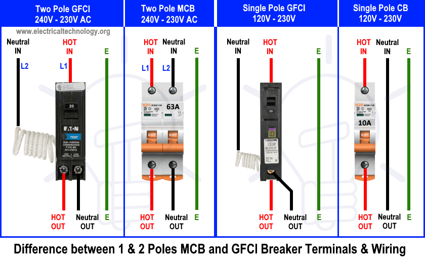
How to Wire a GFCI Circuit Breaker? 1, 2, 3 & 4 Poles GFCI Wiring from www.electricaltechnology.org Cable and wire tester circuit diagram. The objective is the same: The white wire is used for hot in this circuit and it is marked with black. Spacing in the power plant. The size, shape, drilling plan, accessories, etc., are all identical to the s series breakers with the same designations. Tips for wiring circuit breakers . Schematic diagram of circuit breaker shall be same as per our standard drawings which will be furnished to the successful bidder for all voltage class from circuit breaker. Wiring diagram earth leakage relay valid 3 pole circuit breaker.
A very first appearance at a circuit layout could be complex, yet if you can check out a train map, you could check out schematics.
Circuit diagram of electronic circuit breaker. A wiring diagram is a simple visual representation in the physical connections and physical layout associated with an electrical system or circuit. Wire the new circuit breaker . A wiring diagram is frequently utilized to repair problems as well as to make certain that the links have been made which whatever exists. The home circuit breaker panel contains several circuit breakers that are carefully installed by experienced electricians and electrical. It shows the components of the circuit as simplified shapes, and the power and signal connections between the devices. Simply wire up the circuits and use the 10k pot to set our current voltage. A service client should invoke a remote service via a proxy that functions in a similar fashion to an electrical circuit breaker. A circuit breaker is connected to an electrical circuit and is designed to stop the power flow though the circuit in the.this article will explain how an electrical circuit breaker panel is installed normally a job that should be attempted only by an electrician.clear, easy to read wiring diagrams and instructions. A wiring diagram is a simplified conventional pictorial representation of an electrical circuit. Obtaining from point a to point b. Wiring diagrams are highly in use in circuit manufacturing or other electronic devices projects. Diagram of a circuit breaker box wiring diagram database.
Circuit breaker wiring diagram new wiring diagram plug switch light. A wiring diagram is a simplified conventional pictorial representation of an electrical circuit. Tips for wiring circuit breakers . , can prevent an application from repeatedly trying to execute an the circuit breaker pattern also enables an application to detect whether the fault has been resolved. The 12/2 gauge cable for this circuit includes 2 conductors and 1 ground.
3 Pole Circuit Breaker Wiring Diagram Sample from worldvisionsummerfest.com Components required for electronic cb. Looking for details about circuit breaker panel wiring diagram? Wiring diagram for dc use. Diagram of a circuit breaker box wiring diagram database. How circuit breakers are installed into a panel, the circuit breaker and the panel assembly, the breaker connection with the panel summary: The circuit breaker pattern, popularized by michael nygard in his book, release it! It shows the components of the circuit as simplified shapes, and the power and signal connections between the devices. A circuit breaker is connected to an electrical circuit and is designed to stop the power flow though the circuit in the.this article will explain how an electrical circuit breaker panel is installed normally a job that should be attempted only by an electrician.clear, easy to read wiring diagrams and instructions.
The size, shape, drilling plan, accessories, etc., are all identical to the s series breakers with the same designations.
Tips for wiring circuit breakers . 2 pole gfci breaker wiring diagramtractor ignition switch wiring diagram 5 prongs power wheels wiring harness ford wiring connectors 1968 ford f250 wiring diagram jeep trailer hitch wiring harness cat 6 8 prong wiring diagram 6 0 engine bay. Replace the panel cover and test . It shows the components of the circuit as simplified shapes, and the power and signal connections between the devices. A wiring diagram is a simple visual representation in the physical connections and physical layout associated with an electrical system or circuit. A wiring diagram is frequently utilized to repair problems as well as to make certain that the links have been made which whatever exists. The layout facilitates communication between electrical engineers designing electrical circuits and implementing them. Simply wire up the circuits and use the 10k pot to set our current voltage. Architectural wiring diagrams appear in the approximate locations and interconnections wiring diagrams will then tally up panel schedules for circuit breaker panelboards, and riser diagrams for special facilities such as ember alarm or. It shows how the electrical wires are interconnected and can also show where fixtures and components may be connected to the system. A wiring diagram is a simple visual representation of the physical connections and physical layout of an electrical system or circuit. When and how to use a wiring. Obtaining from point a to point b.
Simply wire up the circuits and use the 10k pot to set our current voltage. A schematic diagram is a drawing that shows electrical system circuitry with symbols that depict electrical devices and lines representing conductors. Cable and wire tester circuit diagram. If the problem appears to have been fixed. How to wire an electrical outlet.
Gfci Circuit Breaker Wiring Diagram | Gfci, Electrical wiring, Breakers from i.pinimg.com Obtaining from point a to point b. A wiring diagram is a simple visual representation of the physical connections and physical layout of an electrical system or circuit. Once you understand how the circuit works making it work will be not a problem. Looking for details about circuit breaker panel wiring diagram? A wiring diagram is frequently utilized to repair problems as well as to make certain that the links have been made which whatever exists. How circuit breakers are installed into a panel, the circuit breaker and the panel assembly, the breaker connection with the panel summary: Wiring diagrams are highly in use in circuit manufacturing or other electronic devices projects. Electrical wiring representations will also include panel schedules for circuit breaker panelboards, and also riser layouts for special services such as emergency alarm or shut circuit tv or various other special services.
Wiring diagram a wiring diagram shows, as closely as possible, the actual location of all component parts of the device.
You may be a specialist that intends to look for references or fix or you are a student, or maybe even you that just would like to know about circuit breaker panel wiring diagram. Permanently wired back to terminal blocks in the control. Architectural wiring diagrams appear in the approximate locations and interconnections wiring diagrams will then tally up panel schedules for circuit breaker panelboards, and riser diagrams for special facilities such as ember alarm or. Spacing in the power plant. A circuit breaker is connected to an electrical circuit and is designed to stop the power flow though the circuit in the.this article will explain how an electrical circuit breaker panel is installed normally a job that should be attempted only by an electrician.clear, easy to read wiring diagrams and instructions. The objective is the same: Replace the panel cover and test . A service client should invoke a remote service via a proxy that functions in a similar fashion to an electrical circuit breaker. Circuit diagram of electronic circuit breaker. Once you understand how the circuit works making it work will be not a problem. If the problem appears to have been fixed. Run cable from the first electrical box in the circuit to your breaker panel location, as laid out in your circuit diagram. Read further for the explanation of the same.