Home
› Automatic Water Level Controller Circuit Diagram For Submersible Pump : Yimaker Dc Ac12v Stm8 Full Automatic Water Level Controller Switch Liquid Level Water Pump Board Board Board Board Controlboard Water Aliexpress / Here is a very useful project of an automatic water pump controller circuit.
Automatic Water Level Controller Circuit Diagram For Submersible Pump : Yimaker Dc Ac12v Stm8 Full Automatic Water Level Controller Switch Liquid Level Water Pump Board Board Board Board Controlboard Water Aliexpress / Here is a very useful project of an automatic water pump controller circuit.
Automatic Water Level Controller Circuit Diagram For Submersible Pump : Yimaker Dc Ac12v Stm8 Full Automatic Water Level Controller Switch Liquid Level Water Pump Board Board Board Board Controlboard Water Aliexpress / Here is a very useful project of an automatic water pump controller circuit.. Here is a very useful project of an automatic water pump controller circuit. In this video you will learn how to install water level controller of imagine technologies for single phase submersible starter and three phase dol starter. This controller can be used with single phase water pump motor, and also for 3 phase motor. In the diagram a water level controller shown with a motor starter, a water level sensor with an overhead tank, and an underground tank. The pump will automatically turn on if the water level in the tank decrease (cross the green wire).
• this is an automatic submersible motor controller</p> <p>• the main advantage of this. Blured(101s) automatic watertank overflow control & pump off, 35. Automatic water level controller to turn water pump on / off based on, 36. The water level controller circuit does not. This project is very useful, interesting, and very effective.
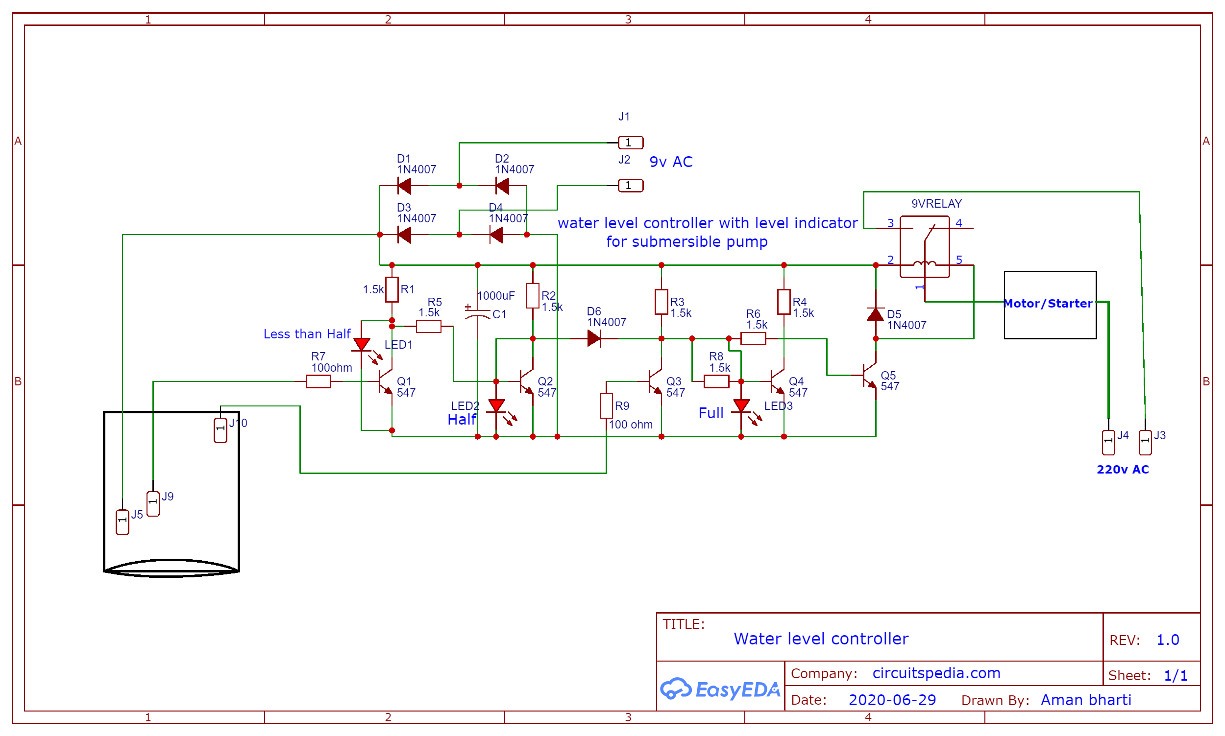
Water Level Controller For Submersible Motor Easyeda from image.easyeda.com In this post, you will learn how to use the water level controller for a tank. This pump activates itself whenever the water level is below an already set level and deactivates when it reaches a maximum level, also set. And there is also an emergency stop switch to stop the water pump. Automatic water level controller to turn water pump on / off based on, 36. This automatic water pump controller also checks the water level of the underground tank, before starting the pump. When the water level rises: In this mini electronics project, i have shown how to make an automatic water level controller for the submersible pump and overhead tank with a 555 timer circuit. Only one led is glowing at one level and other two are in off state.
Automatic submersible pump controller circuit posted here is used to automate the operation of an electrical submersible pump (esp) based on the level of water in the overhead tank.
How to make automatic water pump controller circuit watch the video. How the automatic water level controller circuit works? In the countryside, water is very important. In this post, you will learn how to use the water level controller for a tank. But waste a lot of electricity. I have used the 555 timer ic f. Bc 547 transistor x 3 = 9 inr. In this 555 project, i have explained how to make an automatic water level controller for submersible pump using the 555 timer ic. The brass screws must be adequately tin coated by soldering a layer of solder on them to prevent corrosion. Automatic water level controller circuit diagram for submersible pump motor. The circuit is completely automatic which stops the pump motor when the water level in. Blured(101s) automatic watertank overflow control & pump off, 35. The tank has 3 sensors that indicate the amount of water in the tank to the controller circuit.
In this video you will learn how to install water level controller of imagine technologies for single phase submersible starter and three phase dol starter. Water pump controller with underground and overhead tank automation. Can run the motor manually and automatically using the switch. Bc 547 transistor x 3 = 9 inr. The brass screws must be adequately tin coated by soldering a layer of solder on them to prevent corrosion.
5 Simple Water Level Controller Circuits from www.homemade-circuits.com Fully automatic tank water level control system for motor on & off, 34. What we need is an alternating relay control running p1 and p2 turn by turn. I am using two different circuits for this. Automatic pump controller using 555 timer. The circuit will automatically switch on any water pump / motor when the level of water in a tank reaches below from the required level and automatically switch off the pump after filling the tank. Automatic submersible pump controller circuit posted here is used to automate the operation of an electrical submersible pump (esp) based on the level of water in the overhead tank. Only one led is glowing at one level and other two are in off state. This automatic submersible motor pump controller circuit with three stage level indicator provides the visual and attractive led indication.
I have used the 555 timer ic f.
The level of the overhead tank is indicated using 5 leds, and the pump is switched off when the overhead tank gets completely filled up. In the diagram a water level controller shown with a motor starter, a water level sensor with an overhead tank, and an underground tank. In this video you will learn how to install water level controller of imagine technologies for single phase submersible starter and three phase dol starter. Automatic water pump/level controller circuit with indicator.this project is very useful , interesting and very effective. Here is a very useful project of an automatic water pump controller circuit. Blured(101s) automatic watertank overflow control & pump off, 35. This automatic water pump controller with three stage level indicator provides the visual and attractive led indication as level of water in water tank. This is the driving circuit of the $1 automatic water level controller. Such sensors are more reliable than. The article explains 5 simple automatic water level controller circuits which can be used for effectively controlling the water level of a water tank by switching the pump motor on and off. 1 shows the controller circuit. In the countryside, water is very important. Each sensors float is suspended from above using an aluminium rod.
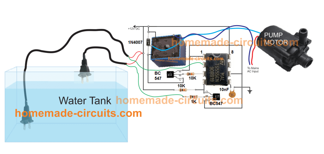
The shown circuit of an automatic submersible pump controller can be understood as given under: What we need is an alternating relay control running p1 and p2 turn by turn. The water level sensor is made with a metal plate mounted on the reservoir or water tank, with a sensor in the short to create the top level and a detection sensor for detecting long again made for the. On next occasion it will be p1's turn and so forth. The controller responds depending upon the relevant levels of water in the tank and the position of the immersed sensor points.
Automatic Water Pump Switch On Off Circuit With 555 Timer from easyelectronicsproject.com Automatic submersible pump controller circuit posted here is used to automate the operation of an electrical submersible pump (esp) based on the level of water in the overhead tank. Total cost of this circuit is equals to 66rs or 66inr (66.6 inr = 1 usd).that means this circuit is under the $1 budget. This controller can be used with single phase water pump motor, and also for 3 phase motor. I am using two different circuits for this. Automatic water pump controller circuit. The tank has 3 sensors that indicate the amount of water in the tank to the controller circuit. The circuit will automatically switch on any water pump / motor when the level of water in a tank reaches below from the required level and automatically switch off the pump after filling the tank. The circuit uses 1 transistor, 1 ne555 timer ic, a relay and few passive components.
Blured(101s) automatic watertank overflow control & pump off, 35.
Next time when the preset level is reached p2 should start and pump the water out. The tank has 3 sensors that indicate the amount of water in the tank to the controller circuit. On next occasion it will be p1's turn and so forth. This is an automatic submersible motor controller circuit using transistor • the main advantage of this project is to all three leds are glowing one by one. Automatic water level controller circuit diagram for submersible pump motor. 1 shows the controller circuit. The automatic submersible pump controller circuit can be used as a standalone system and can also be interfaced to the existing manual control panel. In this video you will learn how to install water level controller of imagine technologies for single phase submersible starter and three phase dol starter. This project is very useful, interesting, and very effective. Submersible water pump circuit diagram posted by margaret byrd posted on november 15, 2017 water pump wiring troubleshooting goulds well diagram full two submersible pumps alternately deep installation automatic level controller for shurflo 9300 9325 083 single phase motors and controls starter residential fuse box Automatic water pump controller with water tank level indicator, 37. Now if you have needed automatic water level controller wiring with diagram for submersible pump motor or with the direct online starter. Automatic water tank level controller motor driver, 38.