Home
› Schematic Diagram Symbols - Circuit Diagram Symbols Electrical Network Elements Cad Block And Typical Drawing : The symbols represent electrical and electronic components.
Schematic Diagram Symbols - Circuit Diagram Symbols Electrical Network Elements Cad Block And Typical Drawing : The symbols represent electrical and electronic components.
Schematic Diagram Symbols - Circuit Diagram Symbols Electrical Network Elements Cad Block And Typical Drawing : The symbols represent electrical and electronic components.. Standard electrical iec symbols also known as iec 60617 (british standard bs 3939) used to represent various devices including pilot lights, relays, timers and switches for usage in electrical. Learn vocabulary, terms and more with flashcards, games and other study tools. Schematics using international symbols may instead use a featureless rectangle, instead of the squiggles. Circuit symbols overview resistors capacitors inductors by using a common set of circuit symbols in schematics, it is possible for electronic engineers. All circuit symbols are in standard format and can be used for drawing schematic circuit diagram and layout.
Electrical circuit schematic symbols are graphical sign, that is used to design electronic, electrical circuit schematic diagram. As you go through various parallax microcontroller tutorials, you will below is a list of common symbols you might see in these schematics. Electronic schematics use symbols for each component found in an electrical circuit, no matter how small. Circuit symbols overview resistors capacitors inductors by using a common set of circuit symbols in schematics, it is possible for electronic engineers. These correspond to the leads (or other terminals).
Electric Symbols Set Of Relays And Electromagnets Complete Vector Set Of Electric And Electronic Circuit Diagram Symbols And Canstock from comps.canstockphoto.com Circuit symbols overview resistors capacitors inductors by using a common set of circuit symbols in schematics, it is possible for electronic engineers. Download high quality circuit schematic symbols images of common electrical and electronics components, for creating any schematic diagram. Standard electrical iec symbols also known as iec 60617 (british standard bs 3939) used to represent various devices including pilot lights, relays, timers and switches for usage in electrical. A schematic diagram is a picture that represents the components of a process, device, or other object using abstract, often standardized symbols and lines. Below is a table of the most commonly used electrical symbols used in schematic diagrams to represent all of the different electronic devices and functions. Electrical circuit schematic symbols are graphical sign, that is used to design electronic, electrical circuit schematic diagram. The components identified by the symbol. How to create electrical diagram using conceptdraw diagram.
Examples of electronic schematic diagrams.
Ir, vf bl(cvf) schematic diagrams. A schematic diagram is a picture that represents the components of a process, device, or other object using abstract, often standardized symbols and lines. An electronic symbol is a pictogram used to represent various electrical and electronic devices or functions, such as wires, batteries, resistors, and transistors, in a schematic diagram of an electrical or electronic circuit. Schematics using international symbols may instead use a featureless rectangle, instead of the squiggles. There is a quite adequate collection of symbol for electrical, electronic circuit. Electronic schematics use symbols for each component found in an electrical circuit, no matter how small. Electrical diagram symbols represents devices and components of electrical and electronic circuits. .of common schematic/wiring diagram symbols used throughout various parts of the world. All circuit symbols are in standard format and can be used for drawing schematic circuit diagram and layout. To be able to read schematics you must know the schematic symbols. Are you ready for a barrage of circuit components? As nowadays there is no single standard, most of the schematic symbols shown here, are. Ciircuits, diagrams & symbols includes:
Electrical symbols are the most commonly used symbols in circuit diagramming. Learn to use digital potentiometers schematic circuits diagram. Standard electrical iec symbols also known as iec 60617 (british standard bs 3939) used to represent various devices including pilot lights, relays, timers and switches for usage in electrical. Ir, vf bl(cvf) schematic diagrams. Schematic diagram * components + each component symbol has some number of connection points to which lines can be drawn.
A Circuit Diagram Symbols Programming Interactivity Book from www.oreilly.com Electrical symbols and electronic circuit symbols are used for drawing schematic diagram. These symbols are essential to be able to read schematic diagrams. In complex diagrams it is often necessary to draw wires crossing even though they are not connected. The components identified by the symbol. A schematic, or schematic diagram, is a representation of the elements of a system using abstract, graphic symbols rather than realistic. Wireless remote camera flash trigger schematic circuit diagram. Schematic diagram * components + each component symbol has some number of connection points to which lines can be drawn. How to create electrical diagram using conceptdraw diagram.
Photos of some common components.
This physics video tutorial explains how to read a schematic diagram by knowing what each electric symbol represent in a typical electrical circuit. A schematic, or schematic diagram, is a representation of the elements of a system using abstract, graphic symbols rather than realistic. These symbols are essential to be able to read schematic diagrams. Ir, vf bl(cvf) schematic diagrams. A schematic diagram is a picture that represents the components of a process, device, or other object using abstract, often standardized symbols and lines. Complete circuit symbols of electronic components. These correspond to the leads (or other terminals). Photos of some common components. In complex diagrams it is often necessary to draw wires crossing even though they are not connected. Ciircuits, diagrams & symbols includes: Electrical circuit schematic symbols are graphical sign, that is used to design electronic, electrical circuit schematic diagram. All circuit symbols are in standard format and can be used for drawing schematic circuit diagram and layout. Examples of electronic schematic diagrams.
Electronic schematics use symbols for each component found in an electrical circuit, no matter how small. The symbols represent electrical and electronic components. How to create electrical diagram using conceptdraw diagram. I like the definition of schematic in wikipedia: Electrical symbols virtually represent the components of electrical and electronic circuits.
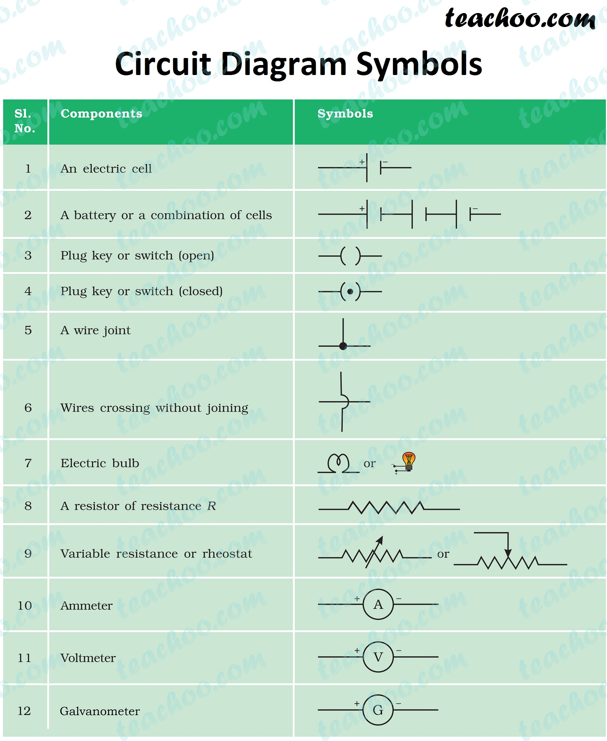
Electric Circuit Diagram Symbol Open And Closed Circuit Teachoo from d1avenlh0i1xmr.cloudfront.net Standard electrical iec symbols also known as iec 60617 (british standard bs 3939) used to represent various devices including pilot lights, relays, timers and switches for usage in electrical. The components identified by the symbol. Ciircuits, diagrams & symbols includes: There is a quite adequate collection of symbol for electrical, electronic circuit. Electrical & electronic symbols and images are used by engineers in circuit layouts and schematic diagrams are a simple and effective way of showing pictorially the. Electrical symbols are the most commonly used symbols in circuit diagramming. Complete circuit symbols of electronic components. Although schematic diagrams are commonly.
Download high quality circuit schematic symbols images of common electrical and electronics components, for creating any schematic diagram.
Circuit symbols overview resistors capacitors inductors by using a common set of circuit symbols in schematics, it is possible for electronic engineers. Electrical circuit schematic symbols are graphical sign, that is used to design electronic, electrical circuit schematic diagram. Electronic schematics use symbols for each component found in an electrical circuit, no matter how small. Solar window charger circuit schematic circuit diagram. Electrical symbols virtually represent the components of electrical and electronic circuits. A schematic, or schematic diagram, is a representation of the elements of a system using abstract, graphic symbols rather than realistic. These symbols are essential to be able to read schematic diagrams. The schematics do not show. As you go through various parallax microcontroller tutorials, you will below is a list of common symbols you might see in these schematics. A schematic diagram is a picture that represents the components of a process, device, or other object using abstract, often standardized symbols and lines. Ciircuits, diagrams & symbols includes: I like the definition of schematic in wikipedia: How to create electrical diagram using conceptdraw diagram.