Home
› Electrical Diagrams Symbols - Auto Wiring Diagram Symbols Rv Water Heater Wiring Diagram For Wiring Diagram Schematics / Electrical symbols virtually represent the components of electrical and electronic circuits.
Electrical Diagrams Symbols - Auto Wiring Diagram Symbols Rv Water Heater Wiring Diagram For Wiring Diagram Schematics / Electrical symbols virtually represent the components of electrical and electronic circuits.
Electrical Diagrams Symbols - Auto Wiring Diagram Symbols Rv Water Heater Wiring Diagram For Wiring Diagram Schematics / Electrical symbols virtually represent the components of electrical and electronic circuits.. Capacitors (parallel lines) store energy in. Ciircuits, diagrams & symbols includes: It wasn't so easy to create electrical symbols and electrical diagram as it is now with electrical diagram. Graphic symbols for electrical and electronics diagrams (including reference designation class designation letters). Electrical diagrams and schematics, electrical single line diagram, motor symbols, fuse symbols, circuit breaker symbols, generator symbols.
There are many electrical and circuit symbols used internationally around the world. A single line diagram shows the distribution path from main. A collection of symbols used on electrical prints. Top must have android apps for electrical. Single line or online electrical diagrams uses these schematic symbols to indicate the paths and components of an electrical circuit.
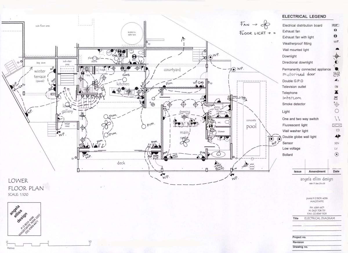
Electrical Plan House Symbols 3 5mm Audio Plug Wiring Begeboy Wiring Diagram Source from www.homedesigndirectory.com.au For example, see symbol 2.1.12.1.1. A3.3 application data referencefor application of these symbols on electrical diagrams, see american national standard drafting practices; Circuit symbols are used in circuit diagrams (schematics) to represent electronic components. This article shows many of the frequently used electrical symbols for drawing electrical diagrams. Ciircuits, diagrams & symbols includes: Graphic symbols for electrical and electronics diagrams (including reference designation class designation letters). In complex diagrams it is often necessary to draw wires crossing even though they are not connected. A collection of symbols used on electrical prints.
Circuit symbols are used in circuit diagrams (schematics) to represent electronic components.
A single line diagram shows the distribution path from main. Wiring diagrams and symbols for electrical wiring commonly used for blueprints and drawings. A collection of symbols used on electrical prints. An electrical device that offers resistance to the flow of charge is generically referred to as a resistor and is represented by a zigzag. All electrical and electronic symbols. Complete circuit symbols of electronic components. Capacitors (parallel lines) store energy in. Collection of circuit symbols, for consultation and interpretation of schematic diagrams of electrical and electronic circuits. In complex diagrams it is often necessary to draw wires crossing even though they are not connected. Basic electrical and electronic graphical symbols called schematic symbols are commonly used within circuit diagrams, schematics and computer aided drawing packages to identify the position of. Circuit symbols are used in circuit diagrams (schematics) to represent electronic components. Graphic symbols for electrical and electronics diagrams (including reference designation class designation letters). Below is a table of the most commonly used electrical symbols used in circuit diagrams.
Electrical diagrams and schematics, electrical single line diagram, motor symbols, fuse symbols, circuit breaker symbols, generator symbols. The actual layout of the components is usually quite different from the circuit diagram. On electrical or electronic diagrams, symbols are used to represent electrical components. Electrical symbols & electronic symbols. Some circuit symbols used in schematic diagrams are shown below.
Lesson 3 T L E Learning Module from gltnhs-tle.weebly.com Electrical symbols and electronic circuit symbols are used for drawing schematic diagram. The actual layout of the components is usually quite different from the circuit diagram. A3.3 application data referencefor application of these symbols on electrical diagrams, see american national standard drafting practices; This article shows many of the frequently used electrical symbols for drawing electrical diagrams. Drawing electrical circuit diagrams, you will need to represent various electrical and electronic devices (such as batteries, wires, resistors, and transistors) as pictograms called electrical symbols. All electrical and electronic symbols. There are many electrical and circuit symbols used internationally around the world. Learn about hvac electrical diagram symbols with free interactive flashcards.
The actual layout of the components is usually quite different from the circuit diagram.
Ciircuits, diagrams & symbols includes: Circuit symbols are used in circuit diagrams which show how a circuit is connected together. Electrical symbols and electronic circuit symbols are used for drawing schematic diagram. Circuit symbols overview resistors capacitors inductors, coils, chokes & transformers diodes bipolar transistors field effect transistors wires, switches. Basic electrical and electronic graphical symbols called schematic symbols are commonly used within circuit diagrams, schematics and computer aided drawing packages to identify the position of. Electronics symbols for schematics and wiring diagrams are mostly universal with a few. The actual layout of the components is usually quite different from the circuit diagram. Learn about hvac electrical diagram symbols with free interactive flashcards. Drawing electrical circuit diagrams, you will need to represent various electrical and electronic devices (such as batteries, wires, resistors, and transistors) as pictograms called electrical symbols. These electrical schematic symbols will help you to identify parts when working with an electrical schematic. It can be used for a zero potential. A3.3 application data referencefor application of these symbols on electrical diagrams, see american national standard drafting practices; Create electrical circuit diagrams and schematics with electrical symbols provided by smartdraw a ground symbol (iec symbol 5017) identifies a ground terminal.
Form with usa standard graphic symbols for electrical and electronics diagrams, y32.2, or other. Single line or online electrical diagrams uses these schematic symbols to indicate the paths and components of an electrical circuit. On electrical or electronic diagrams, symbols are used to represent electrical components. A single line diagram shows the distribution path from main. Wiring diagrams and symbols for electrical wiring commonly used for blueprints and drawings.
Automotive Wiring Diagram Schematic Symbols Legend 95 Honda Accord Lx Engine Diagram For Wiring Diagram Schematics from static-assets.imageservice.cloud Not only do wiring symbols show us where something is to be installed, but what the electrical device is. Some circuit symbols used in schematic diagrams are shown below. It can be used for a zero potential. For example, see symbol 2.1.12.1.1. Amplifiers (denoted by triangle shapes) increase the output signal in your circuit. Circuit symbols are used in circuit diagrams which show how a circuit is connected together. Electrical symbols virtually represent the components of electrical and electronic circuits. Capacitors (parallel lines) store energy in.
Wiring diagrams and symbols for electrical wiring commonly used for blueprints and drawings.
Amplifiers (denoted by triangle shapes) increase the output signal in your circuit. Top must have android apps for electrical. Electrical symbols used today in wiring and ladder diagrams come from national electrical. Not only do wiring symbols show us where something is to be installed, but what the electrical device is. Create electrical circuit diagrams and schematics with electrical symbols provided by smartdraw a ground symbol (iec symbol 5017) identifies a ground terminal. A collection of symbols used on electrical prints. This physics video tutorial explains how to read a schematic diagram by knowing what each electric symbol represent in a typical electrical circuit. The actual layout of the components is usually quite different from the circuit diagram. All circuit symbols are in standard format and they are mostly used to draw a circuit diagram and are standardized internationally by the ieee. An electrical device that offers resistance to the flow of charge is generically referred to as a resistor and is represented by a zigzag. A3.3 application data referencefor application of these symbols on electrical diagrams, see american national standard drafting practices; Capacitors (parallel lines) store energy in. For example, see symbol 2.1.12.1.1.