Ethernet Pinout Diagram - 16 Types Of Computer Ports And Their Functions - Rj45 pinout wiring diagram for ethernet cat 5, 6 and 7.. So, you are trying to find. The original concept was that the centre two pins would be one pair, the next two out the second pair, and so on until the outer pins of. Ethernet cable pinout cat5show all. Nowdays ethernet is a most common networking standard for lan (local area network) communication. It is on pin 9 on the ethernet board because pin 13 is used as part of the spi connection.
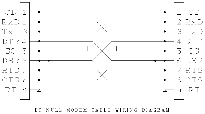
The orange and green pairs of wires are used in both the t568a and t568b. Cables used should be of category 5e(nhanced). Pc serial port is based on rs 232 standard you may find signals details in the rs 232 interface pinout rs 232. The original concept was that the centre two pins would be one pair, the next two out the second pair, and so on until the outer pins of. A ethernet db9 pinout diagram is actually a symbolic illustration of information employing visualization procedures.
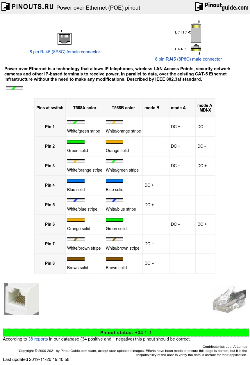
Power Over Ethernet Poe Pinout Diagram Pinoutguide Com from pinoutguide.com Rj45 pinout wiring diagram for ethernet cat 5, 6 and 7. Cables used should be of category 5e(nhanced). Ethernet pinout search.quick and easy to find any pinout diagrams and related information for various types of connectors and cables. Rj45 pinout diagram shows the way how that connector provides communication with network devices. Pinout diagrams and wire colours for cat 5e, cat 6 and cat 7. Ethernet cable pinout cat5show all. A ethernet db9 pinout diagram is actually a symbolic illustration of information employing visualization procedures. Rj45 exists at the end of the ethernet cables that is used for internetwork communication.
The original concept was that the centre two pins would be one pair, the next two out the second pair, and so on until the outer pins of.
Let's describe the role of each. Lowrance ethernet yellow to rj 45 connector the hull scart pinout diagram pinouts ru of arduino micro technologie 8 channel relay module test with mega 2560 youtube arducam esp32 uno board for mini. Remember that pin 1 is on the left hand side of the rj45 connector with the clip at the rear. Pinout diagrams and wire colours for cat 5e, cat 6 and cat 7. Pin signal name 1 rxd_p 2 rxd_n 3 txd_p 4 5 6 txd_n 7 8. It is on pin 9 on the ethernet board because pin 13 is used as part of the spi connection. Moxa technologies nport 5200 serie manual online: Rj45 pinout wiring diagram for ethernet cat 5, 6 and 7. Pc serial port is based on rs 232 standard you may find signals details in the rs 232 interface pinout rs 232. Ethernet pinout search.quick and easy to find any pinout diagrams and related information for various types of connectors and cables. Ethernet cable pinout cat5show all. A ethernet db9 pinout diagram is actually a symbolic illustration of information employing visualization procedures. The orange and green pairs of wires are used in both the t568a and t568b.
You can use any arduino uno pinout diagram as a reference, the one you have found seems to be pretty. Let's describe the role of each. Pc serial port is based on rs 232 standard you may find signals details in the rs 232 interface pinout rs 232. The original concept was that the centre two pins would be one pair, the next two out the second pair, and so on until the outer pins of. The orange and green pairs of wires are used in both the t568a and t568b.
Pinouts Low Voltage Cable Wiring Schemes Showmecables Com from lh6.googleusercontent.com This is the schematic of the physical part of the ethernet connection. Pin signal name 1 rxd_p 2 rxd_n 3 txd_p 4 5 6 txd_n 7 8. Ethernet cable pinout cat5show all. So, you are trying to find. The original concept was that the centre two pins would be one pair, the next two out the second pair, and so on until the outer pins of. Remember that pin 1 is on the left hand side of the rj45 connector with the clip at the rear. A ethernet db9 pinout diagram is actually a symbolic illustration of information employing visualization procedures. Pc serial port is based on rs 232 standard you may find signals details in the rs 232 interface pinout rs 232.
Ethernet cable color coding diagram.
Ethernet home network wiring diagram rj45 ethernet cable pinout. Nowdays ethernet is a most common networking standard for lan (local area network) communication. A ethernet db9 pinout diagram is actually a symbolic illustration of information employing visualization procedures. Rj45 pinout wiring diagram for ethernet cat 5, 6 and 7. Ethernet db9 pinout diagrams have been utilized because ancient. You can use any arduino uno pinout diagram as a reference, the one you have found seems to be pretty. Pc serial port is based on rs 232 standard you may find signals details in the rs 232 interface pinout rs 232. As shown in the diagram the mac peripheral allows connection in a medium indipendent way. Rj45 pinout diagram shows the way how that connector provides communication with network devices. This is the diagram of power over ethernet pinout diagram that you search. Sfp port pinouts and cable specifications. Ethernet pinout search.quick and easy to find any pinout diagrams and related information for various types of connectors and cables. Rj45 pinout wiring diagram for ethernet cat 5, 6 and 7.
Moxa technologies nport 5200 serie manual online: Pinout diagrams and wire colours for cat 5e, cat 6 and cat 7. Ethernet cable color coding diagram. Cables used should be of category 5e(nhanced). Rj45 exists at the end of the ethernet cables that is used for internetwork communication.
Rj45 B Wiring Diagram Free 1971 Chevy Truck Wiring Diagram 1991rx7 Yenpancane Jeanjaures37 Fr from static-cdn.imageservice.cloud Let's describe the role of each. Ethernet pinout search.quick and easy to find any pinout diagrams and related information for various types of connectors and cables. You can use any arduino uno pinout diagram as a reference, the one you have found seems to be pretty. The orange and green pairs of wires are used in both the t568a and t568b. Ethernet db9 pinout diagrams have been utilized because ancient. Ethernet home network wiring diagram rj45 ethernet cable pinout. Sfp port pinouts and cable specifications. Get up to date on the wiring of an ethernet cable with our rj45 connector pinout diagram at warehouse cables!
Rj45 wiring pinout for crossover and straight through lan ethernet network cables.
Ethernet cable color coding diagram. Ethernet home network wiring diagram rj45 ethernet cable pinout. Rj45 exists at the end of the ethernet cables that is used for internetwork communication. Rj45 exists at the end of the ethernet cables that is used for internetwork communication. Rj45 wiring pinout for crossover and straight through lan ethernet network cables. Ethernet pinout search.quick and easy to find any pinout diagrams and related information for various types of connectors and cables. A ethernet db9 pinout diagram is actually a symbolic illustration of information employing visualization procedures. Cables used should be of category 5e(nhanced). Rj45 pinout wiring diagram for ethernet cat 5, 6 and 7. Rj45 pinout diagram shows wiring for standard t568b, t568a and crossover cable! As shown in the diagram the mac peripheral allows connection in a medium indipendent way. Remember that pin 1 is on the left hand side of the rj45 connector with the clip at the rear. Rj45 pinout diagram shows the way how that connector provides communication with network devices.