Home
› Simple Battery Diagram - Simple 12v Battery Charger Circuits With Auto Cut Off : This applies to all old cub cadet, ford, jacobsen, john deere, wheel horse, case, and simplicity garden tractors.
Simple Battery Diagram - Simple 12v Battery Charger Circuits With Auto Cut Off : This applies to all old cub cadet, ford, jacobsen, john deere, wheel horse, case, and simplicity garden tractors.
Simple Battery Diagram - Simple 12v Battery Charger Circuits With Auto Cut Off : This applies to all old cub cadet, ford, jacobsen, john deere, wheel horse, case, and simplicity garden tractors. . Let's take a look at this simple diagram. The following basic wiring diagrams show how batteries, battery switches, and automatic charging relays are wired together from a simple single battery / single engine configuration to a two engine, one generator, and four battery bank system. Hello, friends, this is the best battery level indicator circuit diagram. The circuit is designed as a constant. Proper battery management, including switching and charging, is essential for safe and reliable operation.
Below you will find the basic design of 3 types of battery isolators with the pros and cons of each. We did our best to keep this as simple and as easy to understand as possible. The diagrams below are intended as an overview and some details are missing. The circuit will monitor the voltage of 12 and 9v batteries and indicate by activating an led when the battery level will reach at the preset value. Simple impedance based battery model.
Very Simple Diy Battery Tester Schematics Construction from avtanski.net Watch video for detail battery level indicator circuit. There is also a trickle charge mode circuitry which will help to reduce the current when the battery is fully charged. This ac voltage is rectified and filtered to obtain an unregulated dc voltage used to charge the battery through a relay. The yield voltage can be adjusted with a 50k potentiometer between 4.08v to 4.26v. Simple circuit diagram for beginners. We did our best to keep this as simple and as easy to understand as possible. See the full video for detail. A battery connected to a light bulb as shown below.
This circuit can be used to charge all type of 12v rechargeable batteries including car batteries.
Assume that we are using 12 volt batteries. The battery is charged from a 230v, 50hz ac mains supply. Using the verbal description, one can acquire a mental picture of the circuit being described. See the full video for detail. This circuit can be used to charge all type of 12v rechargeable batteries including car batteries. The circuit is designed as a constant. The first design is a 4 step led voltage monitor circuit using the versatile ic lm324. The circuit is nothing but a 12v dc power supply with an ammeter for monitoring the charging current. 12 volt car battery charger circuit simple 12v circuits using make a gel cell 1 3ah full diy float diagram for gelled electrolyte max 20 rms lead acid 100ah regulated automatic with lm7815 12vdc mobile power heavy duty auto pdf best portable cut off automotive project diagrams 24v alkaline nicad cur and batteries the rv converter guide arduino. Below you will find the basic design of 3 types of battery isolators with the pros and cons of each. First connect the battery across the indicated points, and then plug in the usb connector with your mobile charger or computer's. Simple 12 volt battery charger circuit diagram designed by using few easily available components, and this circuit is suitable for different types of batteries needs 12 volt. There is also a trickle charge mode circuitry which will help to reduce the current when the battery is fully charged.
The circuit operates in a quite simple way. Lead acid battery charger 1 electronics lab com. The basic building blocks of its major components. The battery is charged from a 230v, 50hz ac mains supply. This is a simple car battery charger with indication.
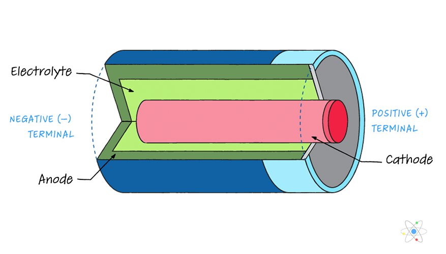
How Do Batteries Work Parts Types Terminology W Diagram from s3-us-west-1.amazonaws.com The battery has two points, anode and cathode. It has to be done based on an algorithm which senses the temperature of the battery and steady decrease in voltage after charge completion. Below you will find the basic design of 3 types of battery isolators with the pros and cons of each. This circuit is designed to provide charging current upto 3 amps and this circuit don't have reverse polarity protection or over. But i wanted to sketch a simple basic solar power system diagram that shows the building blocks. The circuit will monitor the voltage of 12 and 9v batteries and indicate by activating an led when the battery level will reach at the preset value. The yield voltage can be adjusted with a 50k potentiometer between 4.08v to 4.26v. As shown in the diagram, the power supply to the load is through the switching circuit, and therefore the power supply can be cut by keeping the switch open.
12 volt car battery charger circuit simple 12v circuits using make a gel cell 1 3ah full diy float diagram for gelled electrolyte max 20 rms lead acid 100ah regulated automatic with lm7815 12vdc mobile power heavy duty auto pdf best portable cut off automotive project diagrams 24v alkaline nicad cur and batteries the rv converter guide arduino.
Simple circuit diagram for beginners. Here is a basic wiring diagram that applies to all vintage and antique lawn and garden tractors using a stator charging system and a battery ignition system. I received an email from someone scolding me that i was not telling the whole story and claiming the diagrams were simplistic (overly simple). To adjust the circuit for 12v batteries replace the battery in the circuit with an adjustable power supply. This battery voltage is constantly monitored by a feedback circuitry compromised of a potential divider, a diode. Simple 12 volt battery charger circuit diagram designed by using few easily available components, and this circuit is suitable for different types of batteries needs 12 volt. The circuit mentioned in the diagram is built to charge batteries of 12v but it can be adjusted to charge other batteries as well. The post describes 3 simple battery charge monitor or battery status circuits. If the battery is partially discharged, full charge will be attained in one hour. This means that it is made from hydrogen and oxygen. .battery charger circuit diagram gives you a outline design for the general battery charger and circuit diagram. The two diodes forms a centre tapped. Zener diode should be around half of the battery voltage.
The simplest rechargeable battery circuit (and save the planet too)!!!: The battery has two points, anode and cathode. .battery charger circuit diagram gives you a outline design for the general battery charger and circuit diagram. This is a simple car battery charger with indication. This circuit is very simple.
Vector Clipart Dry Cell Battery Structure Diagram Vector Illustration Gg98199413 Gograph from comps.gograph.com The battery is charged from a 230v, 50hz ac mains supply. This battery voltage is constantly monitored by a feedback circuitry compromised of a potential divider, a diode. This applies to all old cub cadet, ford, jacobsen, john deere, wheel horse, case, and simplicity garden tractors. The diode is working as a blocker / current blocker to prevent the current flow back in the ic when there is no voltage on the ic input. The yield voltage can be adjusted with a 50k potentiometer between 4.08v to 4.26v. This diagram shows a simple parallel circuit to increase current or power. For example if you are using it for a 12v battery and you want the circuit to indicate when the The circuit mentioned in the diagram is built to charge batteries of 12v but it can be adjusted to charge other batteries as well.
You can use this circuit with any battery 3.7v/4v/6v/9v/12v etc.
The simplest rechargeable battery circuit (and save the planet too)!!!: A battery connected to a light bulb as shown below. The basic building blocks of its major components. Parallel wiring increases current but the voltage does not change. But i wanted to sketch a simple basic solar power system diagram that shows the building blocks. The circuit is designed as a constant. We did our best to keep this as simple and as easy to understand as possible. H ere is the circuit diagram of a simple and straight forward 12 v battery charger circuit with diagram. It has to be done based on an algorithm which senses the temperature of the battery and steady decrease in voltage after charge completion. This diagram shows a simple parallel circuit to increase current or power. Here is a basic wiring diagram that applies to all vintage and antique lawn and garden tractors using a stator charging system and a battery ignition system. The diagrams below are intended as an overview and some details are missing. The circuit is nothing but a 12v dc power supply with an ammeter for monitoring the charging current.