Home
› Solar Panel Circuit Diagram : A Visual Guide To Off Grid Solar Simplest Possible Design Off Grid Permaculture - The schematic symbol of a solar cell.
Solar Panel Circuit Diagram : A Visual Guide To Off Grid Solar Simplest Possible Design Off Grid Permaculture - The schematic symbol of a solar cell.
Solar Panel Circuit Diagram : A Visual Guide To Off Grid Solar Simplest Possible Design Off Grid Permaculture - The schematic symbol of a solar cell.. Lots of small solar cells spread over a large area can work together to provide enough power to be useful. Step by step pv panel installation tutorials with batteries, ups (inverter) and load calculation. Diy solar panel wiring diagram lovely diy mppt page 9 ecorenovator. All about solar panel wiring & installation diagrams. When you connect wrong polarity, the fuse will blow up.
Solar surface sustainability diagram make it right. Solar panels are wired in series when you connect the positive terminal of one panel to the negative terminal of another. All about solar panel wiring & installation diagrams. Here are controller of solar charger circuit diagram.when connecting a solar panel to a rechargeable battery, it is usually necessary to use a charge controller circuit to prevent the battery from overcharging. Give the connections according to the circuit diagram.
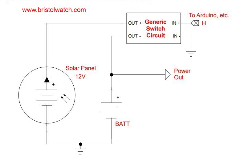
Solar Panel Battery Charge Controller Switching Circuit from www.bristolwatch.com The solar panel block diagram of a power plant for residential use. If you just measure with a voltmeter across the plus and minus leads. Block diagram of arduino based solar panel electrical parameters monitor. The knee of the curves is where the most power is produced, and the voltage & current open circuit voltage is how many volts the solar panel outputs with no load on it. You can easily write code for this circuit using adc of pic microcontroller and lcd display for digital display of these values.if you still have any issue after reading this article, feel free to comment on this post. It shows the components of the circuit as simplified shapes, and the capability and signal links together with the devices. Adjustable solar panel mount mounting rack bracket with large 28 mounting arms boat rv roof off grid. Led solar panel wire diagram intended for solar panel circuit diagram schematic, image size 648 x 651 px, and to view image details here is a picture gallery about solar panel circuit diagram schematic complete with the description of the image, please find the image you need.
All about solar panel wiring & installation diagrams.
Now, as you can see in the circuit diagram pin 11 and 14 are connected to the tip41 transistors for driving the step up transformer. Lots of small solar cells spread over a large area can work together to provide enough power to be useful. In all cases it will be seen that the panel current is very close to constant on any chosen curves while the voltage is varies across its range. Prototype of arduino based solar panel electrical parameters monitor. Step by step pv panel installation tutorials with batteries, ups (inverter) and load calculation. You can easily write code for this circuit using adc of pic microcontroller and lcd display for digital display of these values.if you still have any issue after reading this article, feel free to comment on this post. Block diagram of arduino based solar panel electrical parameters monitor. Step by step pv panel installation tutorials with batteries, ups (inverter) and load calculation. I noticed that you have a. Rated output for solar panels at different light intensities (w/m2). A wiring diagram usually gives instruction more or less the. Charging current = solar panel wattage/solar panel voltage = 5 / 17 = 0.29a. It reveals the parts of the circuit as streamlined shapes, and the power and signal links in between the gadgets.
The right hand diagram shows the result of varying panel temperature when exposed to full sunlight. Then i used your breadboard example and that worked. Voltage produced from solar panel depends upon the intensity of the sun. Lots of small solar cells spread over a large area can work together to provide enough power to be useful. It contains mainly a photovoltaic array ( solar panel );
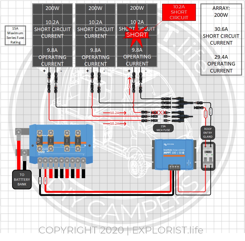
How When To Fuse A Solar Panel Array Explorist Life from www.explorist.life The solar panel block diagram of a power plant for residential use. Home/solar circuit diagrams/solar panel schematic circuit diagram. 1001000 (kilowatt) x 10 (hours) x 30 days 30 kwh hours per month. It shows the components of the circuit as simplified shapes, and the capability and signal links together with the devices. Solar panels are wired in series when you connect the positive terminal of one panel to the negative terminal of another. It contains mainly a photovoltaic array ( solar panel ); Rated output for solar panels at different light intensities (w/m2). This solar panel power switch circuit replaces the diode and connects the panel to battery through a relay contact.
Lots of small solar cells spread over a large area can work together to provide enough power to be useful.
This sun tracking solar panel circuit. Step by step pv panel installation tutorials with batteries, ups (inverter) and load calculation. Voltage produced from solar panel depends upon the intensity of the sun. Then i used your breadboard example and that worked. It reveals the parts of the circuit as streamlined shapes, and the power and signal links in between the gadgets. Inverter, photovoltaic effect, solar charger, solar panel, level indicator. In fact, solar cells are rated by their short circuit current. In all cases it will be seen that the panel current is very close to constant on any chosen curves while the voltage is varies across its range. Here are controller of solar charger circuit diagram.when connecting a solar panel to a rechargeable battery, it is usually necessary to use a charge controller circuit to prevent the battery from overcharging. 1001000 (kilowatt) x 10 (hours) x 30 days 30 kwh hours per month. Some additional circuits are also required for proper measurement. Here lm317 can provide current upto 1.5a.so it is recommended to use high wattage panels if more current is required how to operate this solar battery charger circuit? This solar regulator controller circuit also offers a current control feature, which makes sure that the battery always receives a fixed predetermined charging current rate and is never over driven.
All about solar panel wiring & installation diagrams. All about solar panel wiring & installation diagrams. Step by step pv panel installation tutorials with batteries, ups (inverter) and load calculation. This solar panel power switch circuit replaces the diode and connects the panel to battery through a relay contact. An ammeter is connected in series between diode d1 and fuse to measure the current flowing during charger circuit diagram:
Schematics Wiring Solar Panels And Batteries In Series And Parallel from www.altestore.com Voltage produced from solar panel depends upon the intensity of the sun. The knee of the curves is where the most power is produced, and the voltage & current open circuit voltage is how many volts the solar panel outputs with no load on it. 1001000 (kilowatt) x 10 (hours) x 30 days 30 kwh hours per month. In this circuit all the parameters are in the analog form. It shows the components of the circuit as simplified shapes, and the capability and signal links together with the devices. Things to do before solar panel installation. Diy solar panel system wiring diagram. The solar panel block diagram of a power plant for residential use.
A wiring diagram usually gives instruction more or less the.
Solar panel testing shunt regulator schematic diagram showing all the components including how the the solar panel solar panel testing shunt parts list. 1001000 (kilowatt) x 10 (hours) x 30 days 30 kwh hours per month. Thus the sensitivity of both ldrs can be adjusted by varying the 10k pot shown on the left side of the circuit diagram. All about solar panel wiring & installation diagrams. The produced electrical power from this array batteries are most expensive element of this circuit. The right hand diagram shows the result of varying panel temperature when exposed to full sunlight. Prototype of arduino based solar panel electrical parameters monitor. Then i used your breadboard example and that worked. All about solar panel wiring & installation diagrams. Ive made a simple diagram that shows how each. Give the connections according to the circuit diagram. Diy solar panel system wiring diagram. Posted by on october 27, 2020.