Standard Trailer Wiring Colors - Trailer Wiring Diagram And Installation Help Towing 101 : 15251 south highway 66 unit a.. 7 blade (sae standard) 7 round 6 round vehicle side trailer side time to wire up or rewire your trailer? Contact us to request a bulk pricing quote and dedicated rep support for your business. While none of these are things we look forward to when pulling a trailer, they are also easy to correct. In market there are many special converters 1 2 3 that solves the problem of connecting a car with european wiring to a trailer with north american wiring. Three wires are for the trailer while the last wire is the ground wire.
While none of these are things we look forward to when pulling a trailer, they are also easy to correct. 15251 south highway 66 unit a. Contact us to request a bulk pricing quote and dedicated rep support for your business. Yellow and green are for left and right turns and braking. Standard features * indicates standard options hover to display options *product may vary from photos.
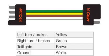
Standard Color Code For Wiring Simple 4 Wire Trailer Lighting Etrailer Com from images.etrailer.com A 4 pin connector is almost always used on trailers that do not utilize electric trailer brakes nor have any need for accessory power and therefore the trailer only requires power for lights. Wiring for ac and dc power distribution branch circuits are color coded for identification of individual wires. It shows the parts of the circuit as simplified shapes, as well as the power as well as signal connections in between the tools. Posted on april 23rd, 2010 by admin. They also provide a wire for a ground connection. This standard makes it simple to locate and trace wiring for the rv's electrical and entertainment systems. In market there are many special converters 1 2 3 that solves the problem of connecting a car with european wiring to a trailer with north american wiring. Yellow and green are for left and right turns and braking.
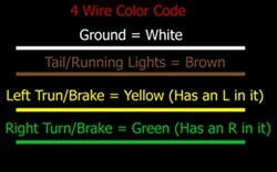
15251 south highway 66 unit a. Variety of dodge trailer wiring diagram 7 pin. The circuits are for left and right brake lights and running lights. Posted on april 23rd, 2010 by admin. Remember, the above colors are just a guide. Three wires are for the trailer while the last wire is the ground wire. Wiring for ac and dc power distribution branch circuits are color coded for identification of individual wires. The four wires control the turn signals, brake lights and taillights or running lights. Most converters allow up to 4 amps to pass through them. To confuse matters worse, typical trailer wire colors are below. Yellow and green are for left and right turns and braking. If you have a trailer with a lot of lights the diode and relay wiring is preferred, but if you have a trailer with a simple light arrangement it is usually sufficient to wire to 58l. Remember that yellow has a l in it so that is the left side brake/turn signal and green has a r in it so that is the right side brake/turn signal.
As the name implies, they use four wires to carry out the vital lighting functions. The funny thing about standards. 15251 south highway 66 unit a. 4, 6, & 7 pin trailer connector wiring pinout diagrams. Remember that yellow has a l in it so that is the left side brake/turn signal and green has a r in it so that is the right side brake/turn signal.
Trailer Wiring Diagram And Installation Help Towing 101 from www.curtmfg.com Contact us to request a bulk pricing quote and dedicated rep support for your business. A wiring diagram is a simplified standard photographic depiction of an electric circuit. • blue reverse lights • green right turn / brakes In market there are many special converters 1 2 3 that solves the problem of connecting a car with european wiring to a trailer with north american wiring. This car is designed not only to travel one location to another but also to carry heavy loads. Remember that yellow has a l in it so that is the left side brake/turn signal and green has a r in it so that is the right side brake/turn signal. Wiring for ac and dc power distribution branch circuits are color coded for identification of individual wires. Yellow and green are for left and right turns and braking.
The funny thing about standards.
It shows the parts of the circuit as simplified shapes, as well as the power as well as signal connections in between the tools. As the name implies, they use four wires to carry out the vital lighting functions. The 5th pin, a blue wire, gives power to operate (or disable) the trailer brakes. 15251 south highway 66 unit a. Remember that yellow has a l in it so that is the left side brake/turn signal and green has a r in it so that is the right side brake/turn signal. The ground wire should be run from the frame of the vehicle to the trailer. A wiring diagram is a simplified standard photographic depiction of an electric circuit. Wiring for ac and dc power distribution branch circuits are color coded for identification of individual wires. Variety of dodge trailer wiring diagram 7 pin. Most converters allow up to 4 amps to pass through them. If you have a trailer with a lot of lights the diode and relay wiring is preferred, but if you have a trailer with a simple light arrangement it is usually sufficient to wire to 58l. They also provide a wire for a ground connection. Yellow and green are for left and right turns and braking.
Manufacturers of equipment, car and auto haulers and tulsa trailers. This car is designed not only to travel one location to another but also to carry heavy loads. Wiring for ac and dc power distribution branch circuits are color coded for identification of individual wires. As the name implies, they use four wires to carry out the vital lighting functions. The red and blue wire can be used for brake control or auxiliary.
7 Pin Trailer Connector Wiring Diagram Tacoma World from twstatic.net The funny thing about standards. Manufacturers of equipment, car and auto haulers and tulsa trailers. A wiring diagram is a simplified standard photographic depiction of an electric circuit. 6 way plug wiring diagr am standard wiring* post purpose wire color tm park lights brown gd ground black (or white) s trailer brakes blue lt left turn/brake light yellow rt right turn/brake light green a accessory red the most common variances on this diagram will be the (blue/brake) & (red/acc.) wires will be inverted. Many trailers have three circuits. 15251 south highway 66 unit a. 4, 6, & 7 pin trailer connector wiring pinout diagrams. Remember that yellow has a l in it so that is the left side brake/turn signal and green has a r in it so that is the right side brake/turn signal.
The worst that usually happens with screwy trailer wiring is a blown fuse on the tow vehicle—or something wacky, like reversed turn signals or blinking brake lights.
Wiring for ac and dc power distribution branch circuits are color coded for identification of individual wires. A 4 pin connector is almost always used on trailers that do not utilize electric trailer brakes nor have any need for accessory power and therefore the trailer only requires power for lights. If you have a trailer with a lot of lights the diode and relay wiring is preferred, but if you have a trailer with a simple light arrangement it is usually sufficient to wire to 58l. What is a 7 way trailer connector? Standard color code for wiring simple 4 wire trailer lighting. 6 way system, rectangle plug 3/4 inch by 1 inch 6 way rectangle connectors right turn signal (green), left turn signal (yellow), taillight (brown), ground (white). Remember, the above colors are just a guide. This car is designed not only to travel one location to another but also to carry heavy loads. To confuse matters worse, typical trailer wire colors are below. Your colors may be different, read the instructions! A wiring diagram is a simplified standard photographic depiction of an electric circuit. The ground wire should be run from the frame of the vehicle to the trailer. The 5th pin, a blue wire, gives power to operate (or disable) the trailer brakes.