Home
› Mobile Charger Pcb Diagram - To Construct a Portable Mobile Charger | Physics Astronomy Project Topics : Finally, after learning how to use eagle to make my own packages and layout a board, i have a pcb.
Mobile Charger Pcb Diagram - To Construct a Portable Mobile Charger | Physics Astronomy Project Topics : Finally, after learning how to use eagle to make my own packages and layout a board, i have a pcb.
Mobile Charger Pcb Diagram - To Construct a Portable Mobile Charger | Physics Astronomy Project Topics : Finally, after learning how to use eagle to make my own packages and layout a board, i have a pcb.. The pcb manufacturing process is very important for anyone involved in the electronics industry. The circuit can charge usb devices with car battery. Mobile phone battery charger circuit. Mobile pcb diagram free download helps you identify mobile phone circuit board original parts and components. The design is quite straight forward, built on a paper phenolic pcb, could be easily repaired.
It is actually a milled board. The design is quite straight forward, built on a paper phenolic pcb, could be easily repaired. Both pcb footprints and schematic symbols are available for download in a vendor neutral format, which can then be exported to the leading eda cad/cae design tools using the ultra librarian reader. Mobile phones, are an essential commodity. Keep the battery connected to the charger and pass power through the additional jst connector using the included cable!
Electrical and Electronics Engineering: USB Mobile Charger Circuit Diagram. from 1.bp.blogspot.com This dc supply can be used to charge mobiles as well as the power source for digital circuits, breadboard circuits, ics, microcontrollers. Circuit mobile charger pcb design mobile charger circuit board customized printed circuit boards mobile charger pcb manufacturer. This is a schematic diagram of a full automatic 12v battery charger for charging the batteries of automobiles etc. Its input is ac220v and gives output dc5v, gives current upto building a charger like that without understanding what a smartphone actually needs to charge it's battery. We are offering electronic mobile charger pcb board to. 1,013 mobile charger circuit diagram products are offered for sale by suppliers on alibaba.com, of which other pcb & pcba accounts for 5%, pcba. It can replenish cell phone battery three or four times in places where ac power is not available. Finally, after learning how to use eagle to make my own packages and layout a board, i have a pcb.
A mobile battery charger circuit is a device that can automatically recharge a mobile phone's battery when the power in it gets low.
• st takes care of the wireless power transfer algorithms and control loop. Keep the battery connected to the charger and pass power through the additional jst connector using the included cable! Every new mobile we buy has its manual in his box. Nowadays mobile phones have become an integral part of everyone's life and hence require frequent charging of battery owing to longer duration usage. The simple 3 amp mobile phone charger diagram can be seen below the circuit of the double dc cell phone charger was successfully tried and built by mr. A very useful project of simple emergency cell phone or mobile charger. Finally, after learning how to use eagle to make my own packages and layout a board, i have a pcb. Mobile phone chargers available in the market are quite expensive. By techgenie in circuits electronics. Solar charger pcb with adjustable output and battery protection. By adjusting its adjust pin, output voltage and current can be regulated. This portable mobile charger is based on the ic lm2576 voltage regulator ic. Printed circuit boards, pcbs, are very widely used as the basis for electronic circuits.
This portable mobile charger is based on the ic lm2576. It can replenish cell phone battery three or four times in places where ac power is not available. 1,013 mobile charger circuit diagram products are offered for sale by suppliers on alibaba.com, of which other pcb & pcba accounts for 5%, pcba. Printed circuit boards, pcbs, are very widely used as the basis for electronic circuits. Solder all the components on a pcb as shown in the circuit diagram.
17: Simulation of wireless mobile charger circuit diagram 17 | Download Scientific Diagram from www.researchgate.net Keep the battery connected to the charger and pass power through the additional jst connector using the included cable! The circuit can charge usb devices with car battery. Mobile phones generally charge with 5v regulated dc supply, so basically we are going to build a circuit diagram for 5v regulated dc supply from 220 ac. Every new mobile we buy has its manual in his box. Its major component is a compact solar panel. Schematic of cell phone charger circuit. This portable mobile charger is based on the ic lm2576 voltage regulator ic. Its input is ac220v and gives output dc5v, gives current upto building a charger like that without understanding what a smartphone actually needs to charge it's battery.
Mobile charger circuit diagram and working principle.
So i want to share pictures of my phone pcb so that u can help. • st takes care of the wireless power transfer algorithms and control loop. Can be built on a general purpose pcb or a veroboard. Every new mobile we buy has its manual in his box. The simple 3 amp mobile phone charger diagram can be seen below the circuit of the double dc cell phone charger was successfully tried and built by mr. Solar mobile charger is a device which can charge mobile phones using solar radiation. This portable mobile charger is based on the ic lm2576 voltage regulator ic. Automatic nimh battery charger circuit. Here is an ideal mobile charger using 1.5 volt pen cells to charge mobile phone while traveling. Mobile phones, are an essential commodity. Ajay dussa over a home designed pcb, the following images of the pcb layout and the prototype were sent by mr. How do lead acid batteries work. Mobile pcb diagram free download helps you identify mobile phone circuit board original parts and components.
Mobile phones generally charge with 5v regulated dc supply, so basically we are going to build a circuit diagram for 5v regulated dc supply from 220 ac. Its input is ac220v and gives output dc5v, gives current upto building a charger like that without understanding what a smartphone actually needs to charge it's battery. A very useful project of simple emergency cell phone or mobile charger. Solar charger pcb with adjustable output and battery protection. The pcb manufacturing process is very important for anyone involved in the electronics industry.
Wireless Charger Circuit - Circuit Diagram Images in 2020 | Wireless charger, Diy wireless ... from i.pinimg.com Mobile charger circuit diagram and working principle. Keep the battery connected to the charger and pass power through the additional jst connector using the included cable! It is actually a milled board. The simple 3 amp mobile phone charger diagram can be seen below the circuit of the double dc cell phone charger was successfully tried and built by mr. These mobile chargers uses only … diagram showing how to read capacitance values of capacitors that use another system of notation on the actual capacitor. Solar charger pcb with adjustable output and battery protection. The project wireless mobile charger circuit diagram posted here can deliver 271ma at 5.2v so you charge mobile phone and also can be used to pcb construction for wireless mobile charger circuit diagram: Mobile phone chargers available in the market are quite expensive.
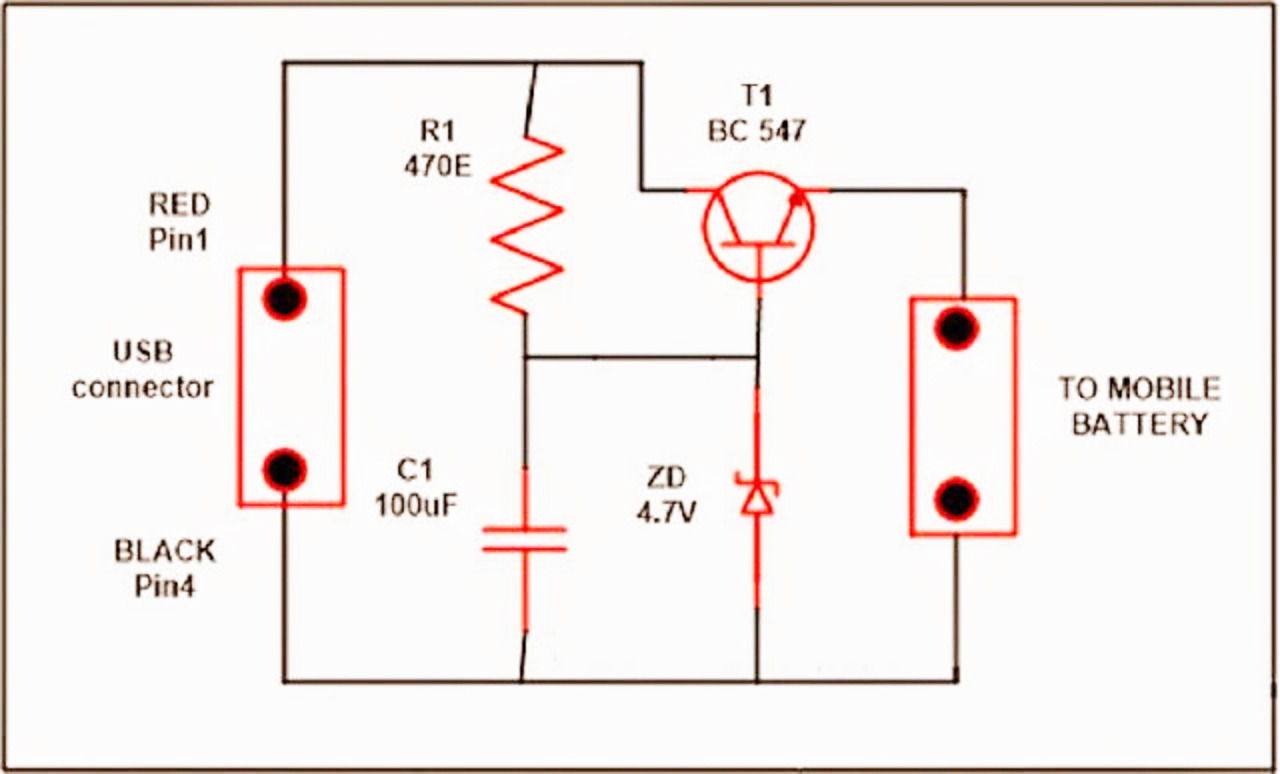
I have designed a mobile phone charger according to following circuit diagram.
A very useful project of simple emergency cell phone or mobile charger. Printed circuit boards, pcbs, are very widely used as the basis for electronic circuits. Solder all the components on a pcb as shown in the circuit diagram. To test the regulator circuit, connect voltage between 8 v and 18v to the input of voltage. On pcb layout, connect to analog ground plane, and only connect to power ground plane through the power pad underneath figure 18 and figure 19 show the timing diagram for signals on the smbus interface. Its input is ac220v and gives output dc5v, gives current upto building a charger like that without understanding what a smartphone actually needs to charge it's battery. So i want to share pictures of my phone pcb so that u can help. I have designed a mobile phone charger according to following circuit diagram. It can replenish cell phone battery three or four times. Here is an ideal mobile charger using 1.5 volt pen cells to charge mobile phone while traveling. By adjusting its adjust pin, output voltage and current can be regulated. Its major component is a compact solar panel. Schematic of cell phone charger circuit.